Anatomy of a modular data center
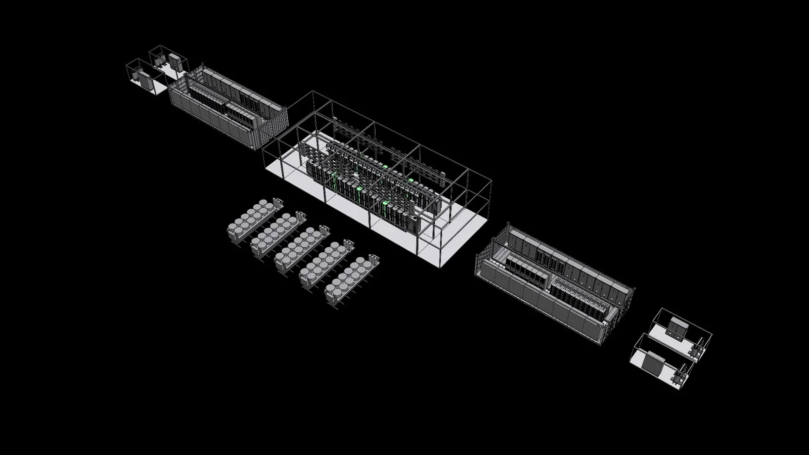
A modular data center is built from blocks: an IT hall for the racks, electrical modules for power, and outdoor plant for cooling. This page takes one example apart. Rotate it, lift off the roof and walls with the Explode slider, or click a part to jump to its view.
Reference design The model is Eliovp's ModFlex reference design. It is illustrative, not a CAD export. See ModFlex on eliovp.com.
Structure
The IT hall is a steel frame on a foundation, with wall panels and a roof that falls gently to a front gutter. With double-width racks the hall is 18 m long and 8 m wide. With single-width racks the same rows fit in 15 m, and the walls, roof and power pods move in with them. The hall, the two power pods and the outdoor plant are separate modules, so they can be placed to suit the site.
The Explode slider lifts the unit apart in three stages: first the shell and frame, then the services (busbars and pipework), then the equipment inside the racks and pods.
Racks
Two rows of racks run along the hall with an aisle between them. In the default layout each row has four double-width compute racks, in the style of AMD Helios, and three single-width storage racks, and every rack has a cooled rear door. One out-of-band (OOB) rack carries the management network. It stands in a service bay at the end of the aisle and reaches every other rack over its own cable route.
Switch to single-width racks to see a layout built around NVIDIA Vera Rubin NVL72, where each rack holds 72 GPUs and 36 CPUs. It has eight compute racks, plus separate racks for context storage, the network fabric and ordinary storage.
Power
Power comes from the two power pods, one at each end of the hall. Each row has four overhead busbars, enclosed metal bars that carry current along the row. A1 and A2 come from the west pod and B1 and B2 from the east pod, each on its own feeder run. Tap-off boxes clip onto the busbars and send cables down to the racks: in the model they are rated up to 160 A for the double-width compute racks, and the storage racks use red 125 A three-phase connectors.
Real ratings depend on the servers and the project. The lab shows what happens when one power path fails.
Cooling
Most of the heat leaves in water. A facility loop runs from the dry coolers outside to the in-row CDUs (coolant distribution units). Each CDU hands the heat over to a separate loop that runs to cold plates on the chips, so facility water never enters a rack.
Some heat still ends up in the air. Rear-door heat exchangers, water coils with fans on the back of each rack, catch it on a third loop with its own distribution skid outside. In the single-width layout, manifolds in each compute rack carry the liquid to the trays, and only the storage racks have rear doors.
How cooling is studied walks through Eliovp's CFD study of the air in a ModFlex room: where it flows, where it warms up and how the pressure varies.
Power pods
Each power pod is an electrical module fitted out in the factory. Inside are the switchgear, UPS modules, battery cabinets and a maintenance bypass, which lets the UPS be serviced while the load stays powered. Overhead cable routes, ventilation, monitoring and red fire-suppression cylinders fill out the module, and solar panels on the roof are an option.
Sources
Adapted from the 3D explorer on Eliovp's ModFlex page.